Installing a Front Sway Bar to an Austin A30/A35

I recently added a front sway bar to my 1952 A30 AS3.
I discovered some time ago, the rear sway bar from a Holden UC Torana or Sunbird ('78 to '80), would fit directly onto my A30, almost as if it was built for this dual purpose.
I was parting-out a UC Torana that was given to me after rotting out under some trees for 8 years (shame), and when I was taking out the rear axle, I thought the width of the sway bar looked pretty close to the width needed to span between the lower wishbones of an A30/A35. The rest of the profile also looked like it would reach far enough forward, to cross over under the sub-frame and clear the radiator and front of the engine.
At about the same time, I acquired an A35 which I intended to restore. This was a good, complete, very straight car, but would require substantial work underneath to repair rust, as the vehicle had lived near the sea for a long time. Shortly after that, I was offered a very good condition '52 A30 that was an ex-Canterbury car and had no rust problems at all, but needed mechanical work to replace many worn out original parts.
After mulling over this dilemma, I decided to take the A30 and use the A35 as a donor car. It was really a no-brainer cost-wise, as the structural work and re-paint of the A35 was not going to be cheap!
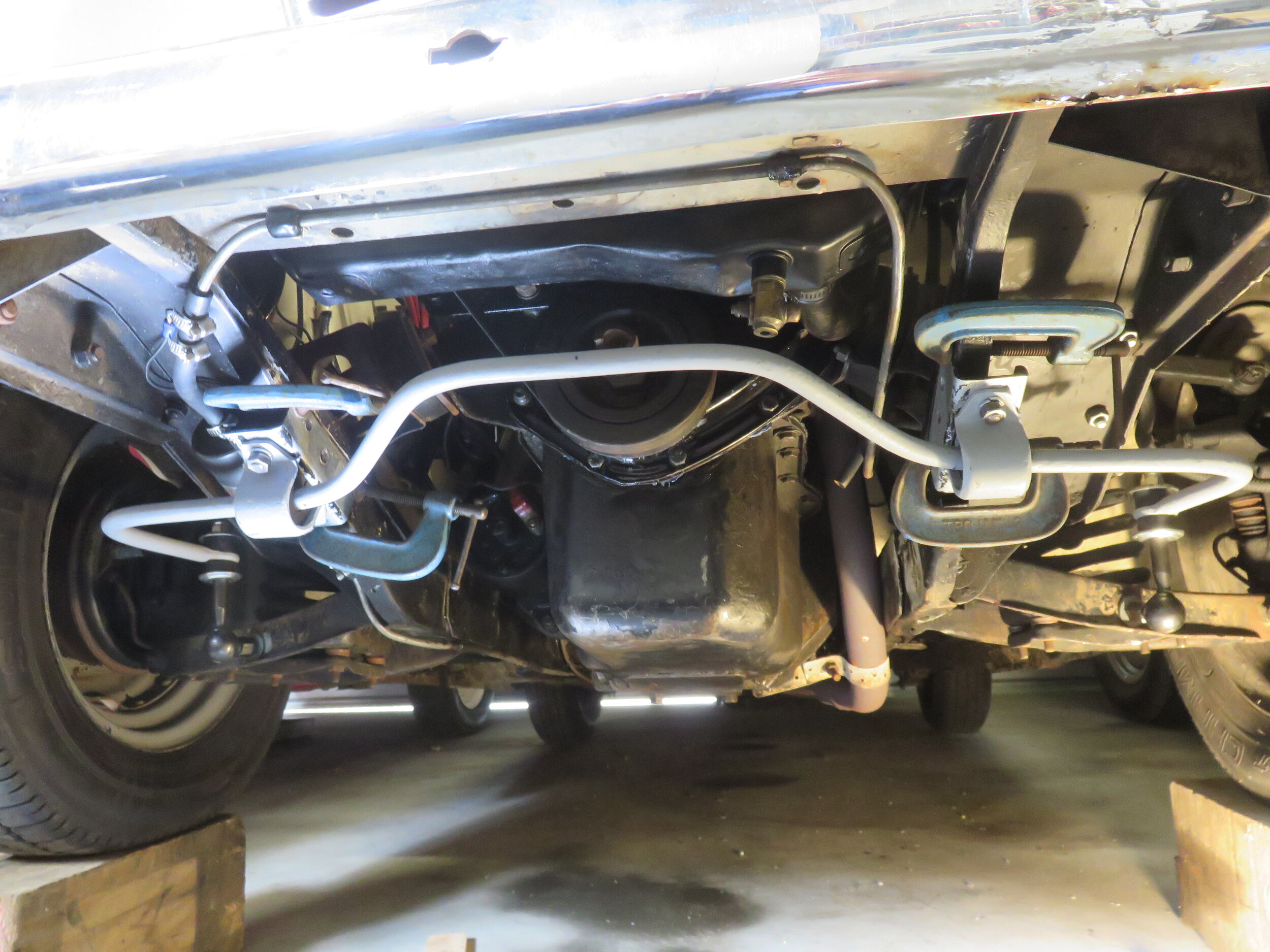
So, while the running gear was still in the A35, I slung the Torana sway bar under the front and tied it up in place with wire, allowing for where the outside knuckle-ends would be positioned and also where the attachment brackets would be in relation to the car's sub-frame. I also turned the sway bar over so the frontal part of the bar swept upwards, rather than down, as it had been on the Torana. It all seemed to fit perfectly. The only thing that was going to be a close call, was whether the sway bar would be clear of the tyres when the wheels were on full-lock. But with the bar tied tightly in position, it looked like it would clear, just.
The sway bar was then hung up in the shed, to be brought out at a later date, when I had done all the fettling needed on the A30 and the A35 was completely parted-out and its remnants gone.
A few weeks ago after putting all new brake lines and an in-line booster system into the A30, I decided to get the Torana rear sway bar down again and fit it onto the car. I had ordered new reproduction Triumph 2000 knuckle-ends from Hawkswood Classics in Auckland. Theseknuckle-ends were originally fitted to many Triumph cars and other British models. They cost just under $70 a pair, plus a couple of dollars shipping.
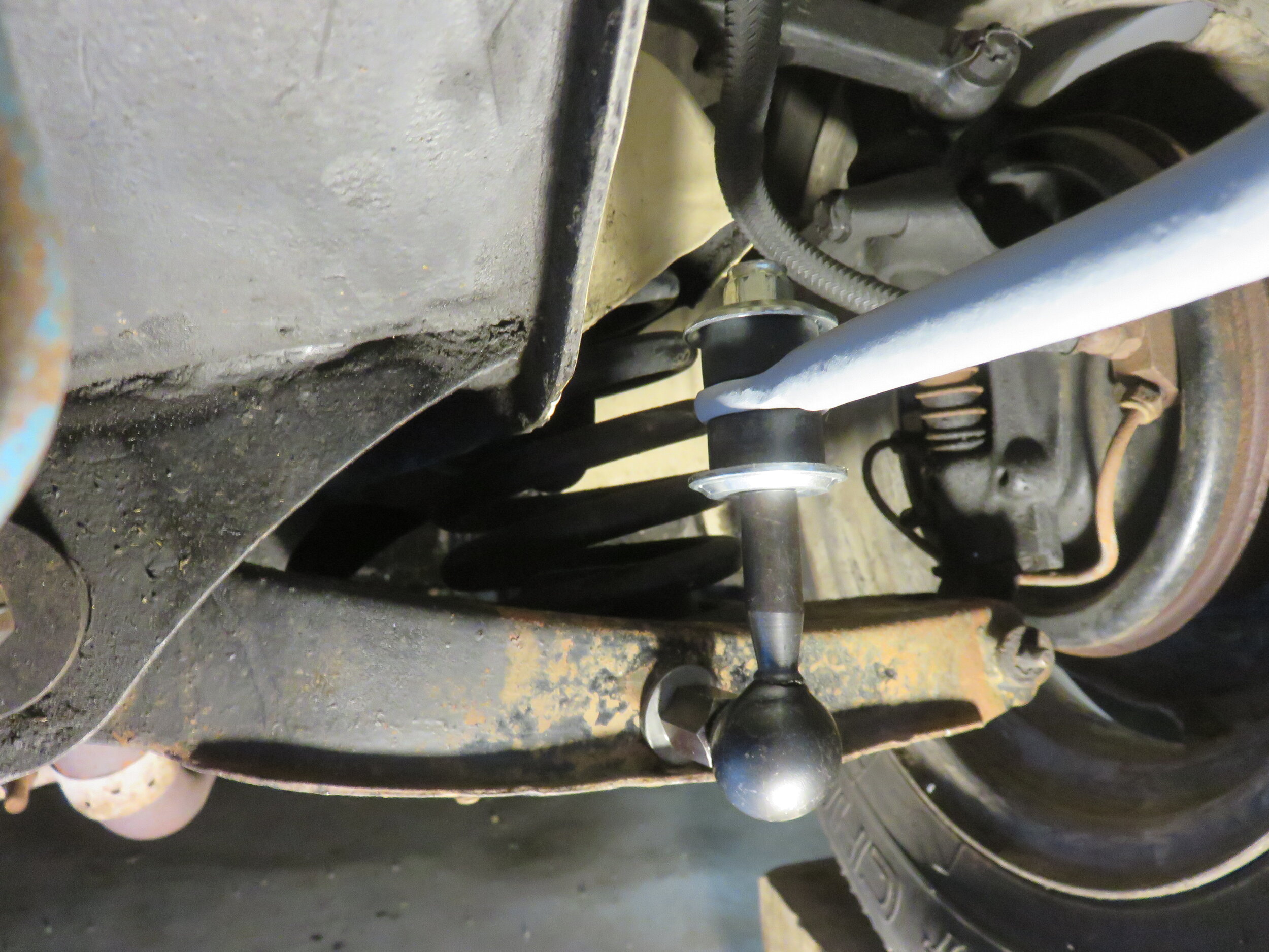
When the knuckle-ends arrived, I measured 115mm from the beginning of the fold of the strengthening lip on the wishbone at the sub-frame end, and made a mark on the under-side of the lip. I then used a builders square to scribe a vertical line on the side of the wishbone. I then measured 15mm up this line from the strengthening lip, made a mark, then centre-punched this point to drill a hole through for the 3/8" stud on the knuckle-end to be attached. These measurements need to be pretty accurate on both wishbones, for centralising the sway bar and also to prevent the 3/8" stud on the knuckle end from fouling on the coil spring recess in the wishbone. It is advisable also to do your drilling in three to four stages of 'drill sizes'. This not onlymakes drilling easier, but also helps keep accuracy. When bolting the knuckle-end studs to the wishbones, I used a 3mm thick galvanised flat washer against the front face of the wishbone for added stability, then a thinner flat washer at the back, followed by the spring washer and nut. Make sure the knuckle-ends are standing perpendicular before tightening home.
After the knuckle-ends were fixed in place, I dropped the sway bar over them, putting the rubbers and caps (washers) in place. These were then screwed down by hand, just enough to hold them in place at present. The sway bar was then held up at the front with lacing wire.
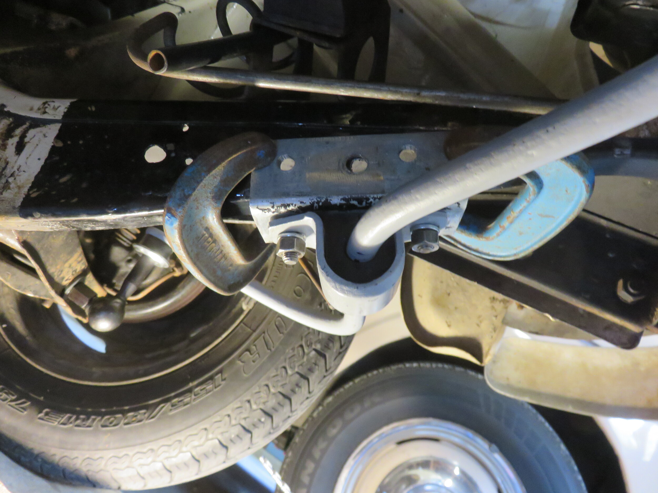
I then assembled the Torana mounting brackets to the sway bar, first lubricating the 'rubbers' to allow easier sliding along the sway bar into the final position, which is right at the bend for the forward section of the sway bar. The 3mm galvanised steel "L" brackets I had made up for bolting to the sub-frame were then bolted to the sway bar brackets, but not tightly. The sway bar with all brackets attached, was then offered up to the sub-frame for final adjustments, with vice-grips being used to attach the "L" brackets to the sub-frame in their correct position. I then used small G-clamps to hold the "L" brackets tightly in position, removing the vice grips as I went.
I then marked and centre-punched the "L" brackets for drilling and bolting to the sub-frame. I chose to use 3 bolts on each side for added strength. Just be careful not to place your centre-punch markstoo close to the strengthening fold on the sub-frame, so a bolt head coming through from the other side won't foul the lip.
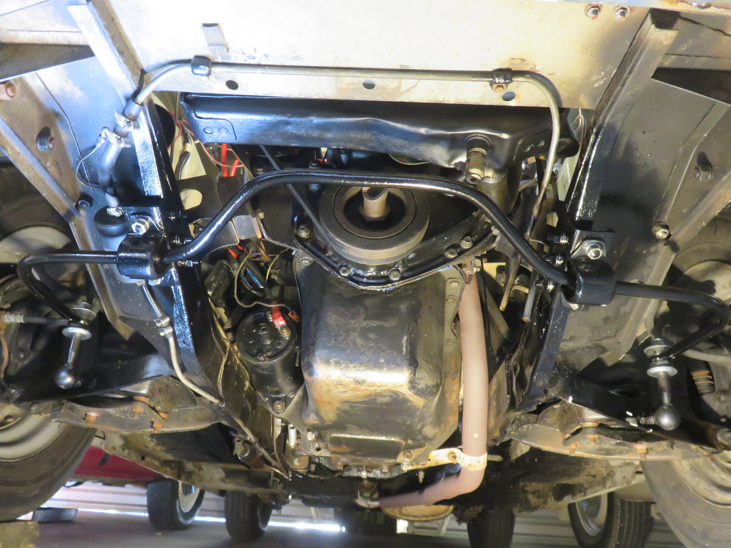
There is not a lot of room left now to drill the "L" bracket holes and through the sub-frame. I didn't want to disassemble anything now to help get it done, as the final position would have to be carefully set-up again to drill through the sub-frame. With a battery drill that is not too large, all drilling can now be done in-car, but you will have to work around the engine front pulley a bit to get the holes right through. Once again, start with a small 'pilot hole' and work your way up, in my case to 5/16". Sharp drill bits will definitely make this task easier.
Once all this was done, I bolted the "L" brackets into their final tightened position, so they could be left on the car. The G-clamps were removed as I did this.
As I still had to give the sway bar a final coat of paint, I carefully undid the bolts holding the sway bar brackets to the "L" brackets, so as not to disturb them too much. The brackets will hold onto therubbers okay when unattached. Holding the sway bar up by hand, I undid the nuts on the outer ends of the sway bar by hand, lifted off the top caps and rubbers, then lifted the sway bar off.
After final painting, the sway bar was carefully re-attached, outer ends placed on first and hand tightened, then the sway bar mounting brackets were put back up to the "L" brackets. Everything can then be finally tightened up. For longevity of the rubbers connecting the outer ends of the sway bar to the knuckle-ends, it pays not to over tighten them. A guide figure for doing this if you have a torque wrench handy, is 12 ft lbs, or 16 Nm. If you are an 'old hand' at doing car work, with decades of experience, you will probably be able to feel how much torque this is, through your ring spanner!
The wheels came to within 5-10ml of the sway bar when on full lock, so plenty of clearance there, considering you are very rarely turning that tightly. The car is also noticeably stiffer when doing a 'bounce' test on each side. In the last photo, you will notice some white marks on the bottom left-hand wishbone. I put these on as an indicator of where the 115mm horizontal, and 15mm vertical measurements are taken from.
Overall, a reasonably easy and cheap way to help keep an A30/A35 standing more upright in the corners, although I do realise that rules in some countries may require the 3mm stability washer on the frontside of the wishbone to be spot welded, or even a small plate made up and welded on. Also, the "L" brackets may have to be welded onto the sub-frame as well, rather than bolted. It's a shame that the rules for these additions are so "generalised", after all, the A30/A35's are a very small, light car, so consequently do not generate anywhere near the forces of much larger vehicles.